How to flash BIOS to device with BIOS guard.
Why you may need it?
Some devices are capable of flashing modified BIOS using internal flash tool if it is your case this tutorial is not for you.
In my case NUC was protected with BIOS guard and only signed code could be flashed with internal flash tool.
If you are familiar with Flash Programming Tool it also failed because of write protection.
I have tested it in multiple modes (from Windows, from Linux, from EFI)..
Finally I have bought hardware programmer and successfully flashed my device.
What programmer and why?
I’m going to describe how to flash device BIOS using RT809F hardware programmer. It is available on ebay and aliexpress.
It is not cheapest one but it is know to work in ISP (in system programming) mode.
I don’t know how cheaper programmers will work (CH341 for example).
I had to updated microcode in multiple devices so I couldn’t imagine desoldering BIOS chip each time new microcode
would be released (that procedure would be required on every update for all devices).
That is why I selected ISP programmer - it is capable of programming chips without requirement of desoldering.
Standard hardware programmer (especially one connected only to USB port which doesn’t have it’s own power supply) can’t
supply enough power to entire board. After you connect to chip which is not desoldered voltage is shared with other
components on board which leads to failures in programming.
Disclaimer
This task is one level further than simple modifing BIOS using internal flash tool.
Here you can brick your hardware unrevertably. Especially if you supply wrong voltage or twist chip power pins.
I’m presenting this mainly to show it is possible, but I do not take responsibility for broken hardware.
You are doing anything for your own risk.
I personally flashed 50 devices using this method without any issue.
Known issues
After flashing some devices (NUC) it is impossible to use internal flash tool.
You need to first return BIOS to original and next try to flash official update.
Prepare
First of all - lets check required parts.
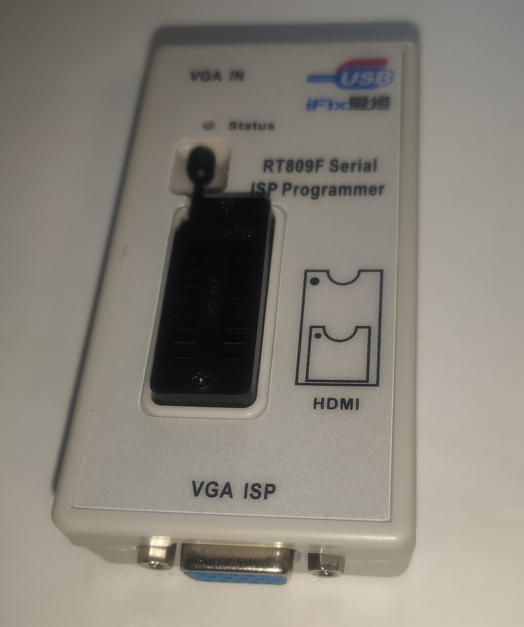
RT809F programmer itself ;)
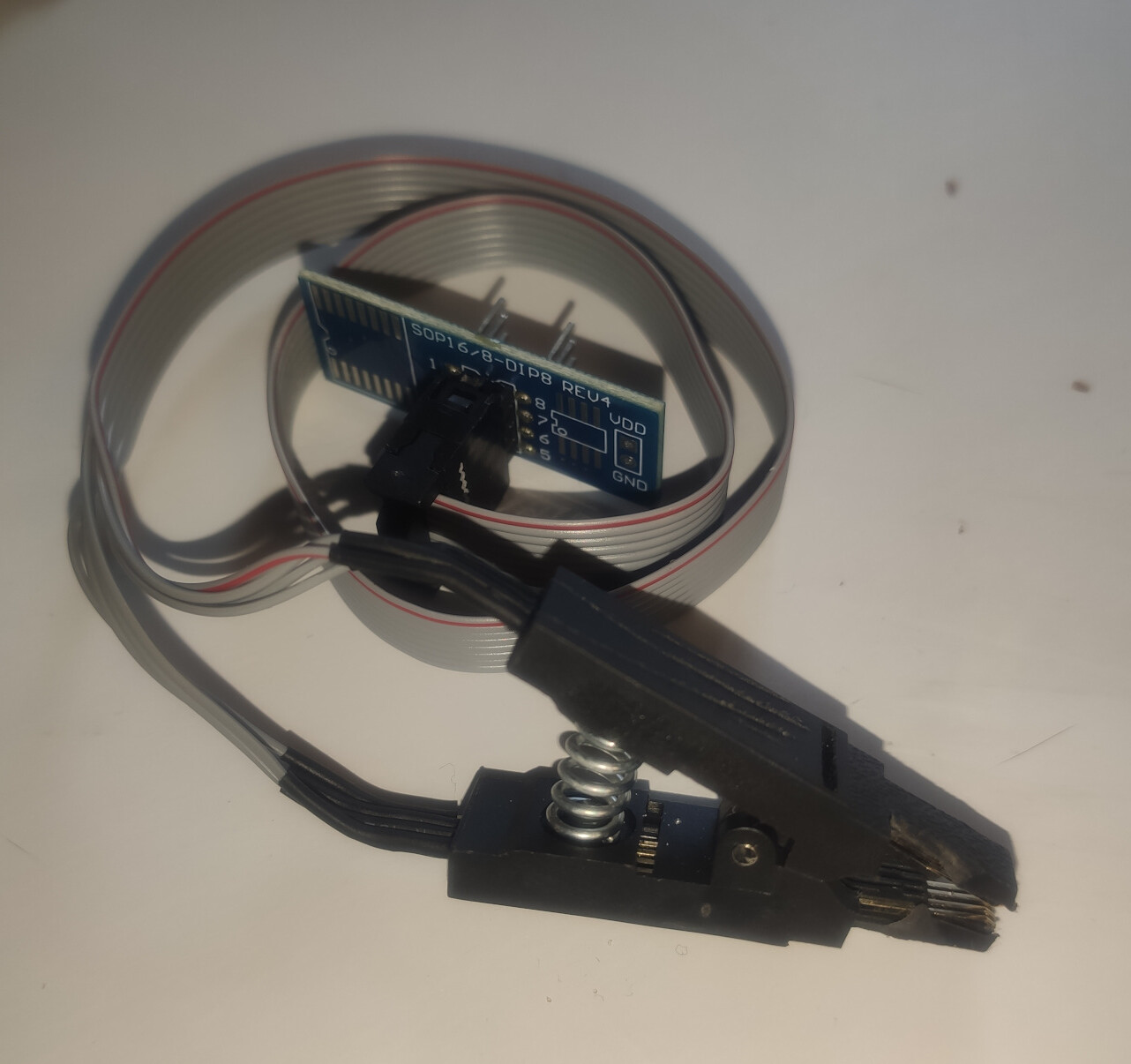
SOIC8 clip (in almost all packages)
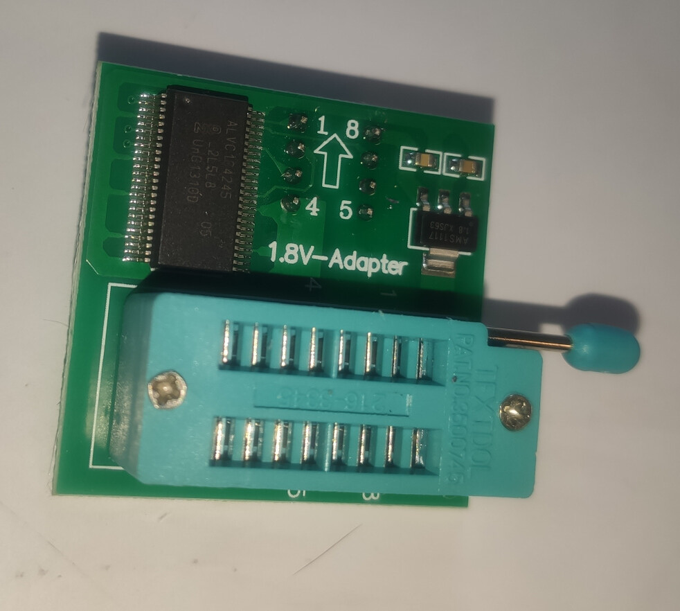
1.8v adapter in case you have such chip. Programmer works on 3.3v level
Connecting programmer with accessories
Depedning on BIOS chip voltage you need to use voltage adapter.
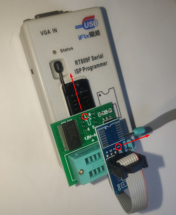
If so you need to place adapter to bottom pins of programmer and clip plug into top pins of adapter.
Always make note to properly orient boards - pin 1 should always point top left side.
As you can see on photo above pin 1 is always pointing to top of socket.
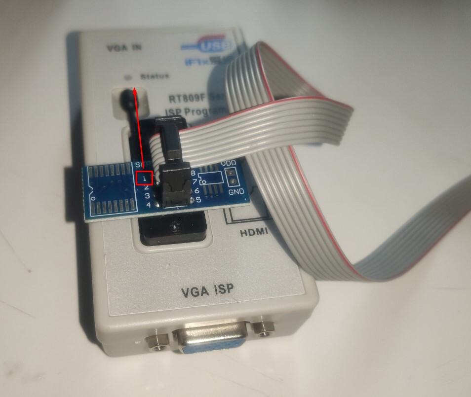
If you don’t need adapter - just put SOIC clip connector into bottom of programmer - always pointing pin 1 to top of socket.
Now you can connect programmer into your working computer using USB cable.
Software
Download software including driver here (all links points to the same soft):
(I suggest to use google translate ;) if you are not familiar with Korean)
Install and run RT809F.exe

After first start soft will probably run in chiness language - in order to change it to EN select english from menu
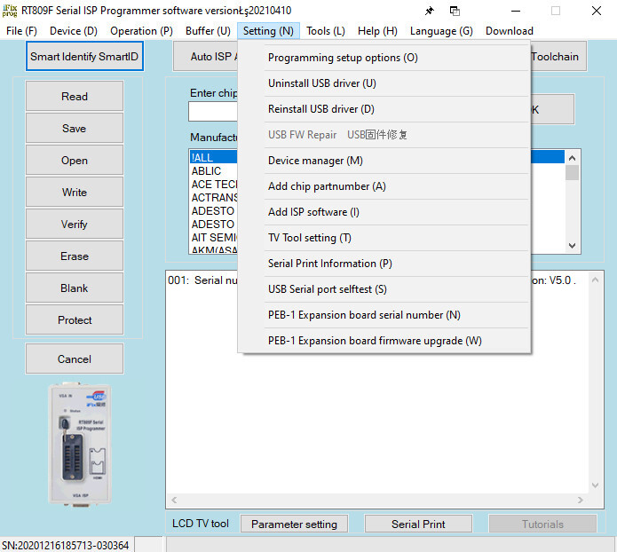
From setting menu select driver installation.
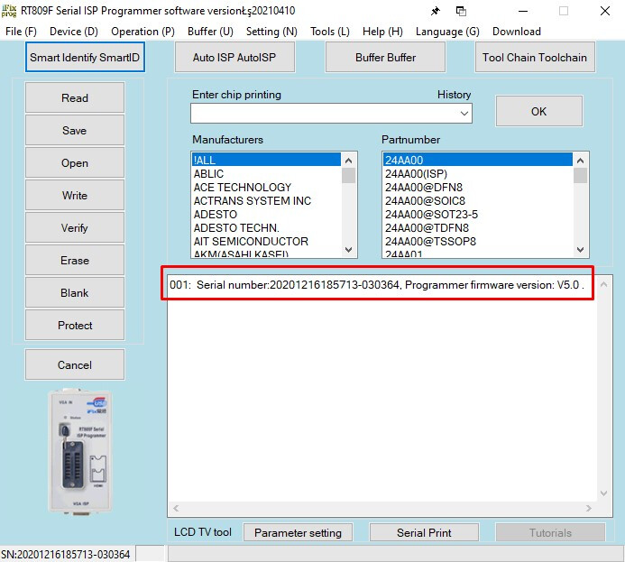
After successful installation you should be able to detect programmer device.
Now programmer is ready to work.
Programming procedure
Note: All steps will be presented on NUC7PJYH.
For your board it may vary ;) which should be obvious.
-
Unplug all subdevices from your MOBO, for best access just take it off from cover.
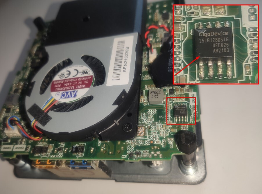
Find BIOS flash memory chip. On my board there were 2 such chips - you will need to figure out which contains BIOS (after reading BIOS is should be easy). -
Plug in power cord to your MOBO and power on PSU.
If you have configured your BIOS to power on device after power failure it will probably start now.
But we need to power it down - just press power button and wait for it to shutdown.

3. Now connect clip to flash chip. Make sure you properly orient PIN 1 (it is marked on chip with dot - check first photo above).
1 pin of clip is marked with red line.
Making mistake here may lead to breaking chip and bricking entire board. Check it twice!!
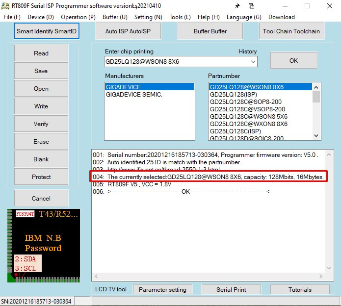
4. Click “Smart identify SmartID” and soft should find closest possible chip. BTW. NUC uses 3 different chips and your boards may use more different chips ;)
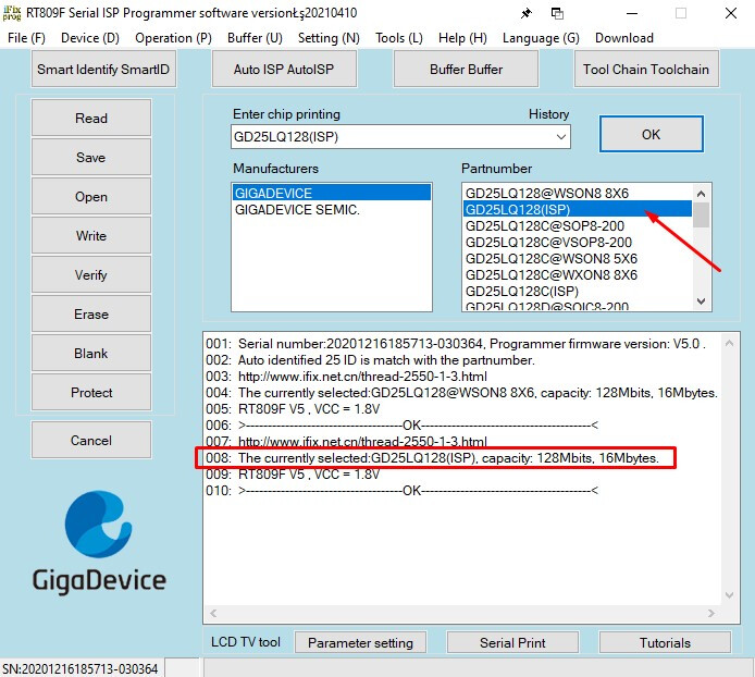
5. Change it to ISP version! (double click on list)
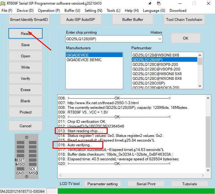
6. Start reading current BIOS. This is very important step! Backup your original BIOS before any further step.
Program will automatically verify read BIOS and if everything was properly read it will give you option to save it.
It is nice cuz RT809 should inform you if there is issue with poor connection (check tip below) or reading was just not successful.
- Modify your BIOS - for example using Kruisdraad tutorial. BTW. BIOS dumped using this method will be probably cleaner than publicly accessible version.
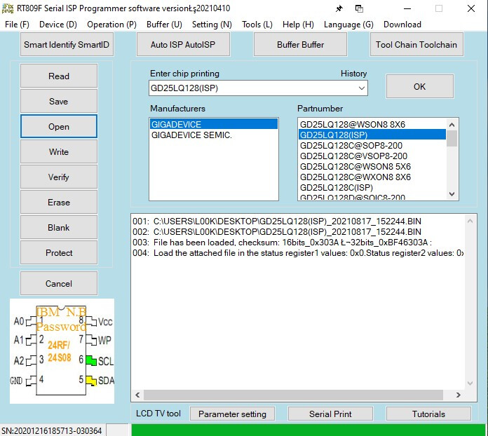
8. Open modified BIOS.
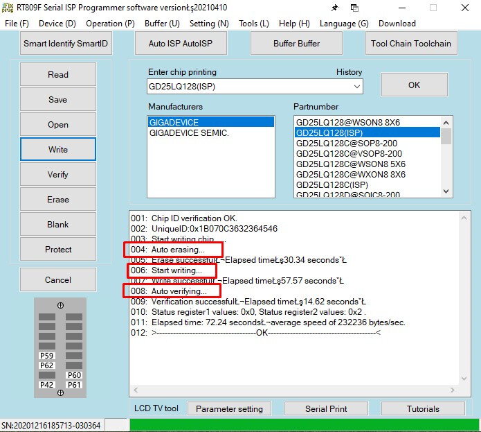
9. Start write.
It will proceed with multiple tasks: ereasing, writing, verifing.
-
After successful flashing you can unplug clip.
-
Unplug power cord for a while. Plug in back and verify is it working.
In case of any issue try to reflash device back with original BIOS.
Tips

-
If you have poor connection on clip you may try to extend “legs” of clip - I have just pull it from inside of clip using scissors.
-
Nice video about using RF809F
https://www.youtube.com/watch?v=Pyp6XtqbdSU